Types
Position
Layout
blog
In networks where XLPE and PILC cables share the same circuit, selecting the wrong joint type is not a minor specification error — it is a guaranteed path to failure.
Most cable joint failures are not random events. When you examine the forensics — the charred resin, the tracked insulation, the failed oil-stop — a pattern emerges. The wrong joint was specified, or the right joint was installed badly, or both.
In established power networks, where cables from the 1970s and cables installed last year sit in the same trench and feed the same substation, this decision comes up regularly. A section of ageing PILC is replaced with modern XLPE. A new 33kV feeder must connect to a legacy ring main. The circuit looks straightforward on the drawing. The jointing interface is where the engineering challenge actually lives.
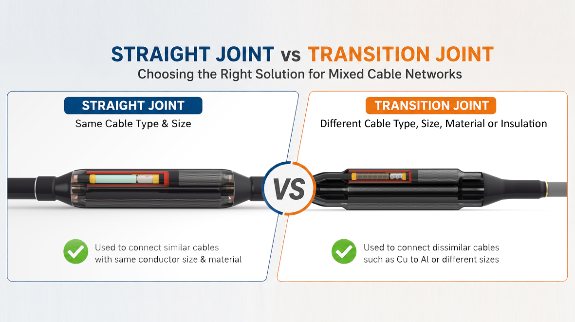
The question is simple to ask: straight joint or transition joint? The answer requires understanding what each joint is actually doing — not just mechanically, but electrically, thermally, and chemically.
A straight joint (also called an inline joint or cable splice) connects two lengths of cable of the same type. Same insulation system. Same voltage class. Same or closely compatible conductor cross-section. Its job is to restore the cable to its original condition: conductor continuity, insulation integrity, screen continuity, and sheath sealing.
Available technologies — pre-moulded push-on, cold shrink, heat shrink, and resin-filled — each suit different site conditions and voltage levels. Pre-moulded silicone bodies are the preferred choice for MV and HV applications where thermal cycling is significant; their elastic recovery maintains constant interface pressure across decades of service. Every one of these technologies rests on the same assumption: both cable ends are the same. When that holds, a straight joint is reliable and cost-effective. The problems start when it does not.
A transition joint connects two cables with incompatible insulation systems — most commonly XLPE to PILC, though XLPE-to-EPR and similar combinations arise in industrial applications.
The need for transition jointing arose from history. PILC cable dominated underground networks through the 1980s and a great deal of it is still in service. XLPE became the standard for new installations from the late 1980s onwards. Today, virtually every mature network contains both. When a PILC section must be replaced, the new XLPE has to connect to the remaining PILC at each end. A straight joint cannot do this — the insulation systems differ fundamentally in their electrical, thermal, and chemical properties, and a straight joint makes no provision for any of those differences.
The transition joint bridges that gap — and it has to do so across four distinct engineering challenges simultaneously.
Oil-stop integrity. PILC cable is impregnated with mineral oil that keeps the paper insulation electrically stable. XLPE is a dry, extruded polymer. Oil contamination of XLPE degrades its dielectric properties and accelerates failure. A properly designed transition joint incorporates an internal oil-stop barrier — typically a moulded rubber plug or resin seal — that prevents migration from the paper end into the XLPE. If this barrier fails, degradation at the interface begins immediately. In field practice, inadequate oil-stop management is one of the most consistent causes of transition joint failure.
Electric stress at the insulation interface. XLPE has a relative permittivity of approximately 2.3; PILC sits between 3.5 and 4.0. At the interface between the two systems, this discontinuity concentrates electric field stress in ways a standard straight joint geometry cannot manage. Transition joints address this through profiled rubber bodies for geometric stress relief, supplemented in higher-voltage designs with resistive field grading materials. This is not engineering that can be improvised on site.
Differential thermal expansion. XLPE operates at a maximum conductor temperature of 90°C; PILC is rated at 80°C. Under load cycling, the two cable ends expand and contract at different rates. The joint body must accommodate this movement — repeatedly, over decades — without losing the interface pressure that maintains electrical integrity. Pre-moulded silicone rubber handles this well. Rigid resin systems do not, which is why they are unsuitable for thermally cycled XLPE–PILC interfaces.
Screen and sheath continuity. PILC cable has a lead sheath serving as both metallic screen and moisture barrier. XLPE typically uses a copper wire or tape screen. The transition joint must manage electrical screen continuity across the interface, ensure the earth path carries fault current, and align with the circuit's bonding strategy — whether solid, single-point, or cross-bonded. This must be designed in advance, not resolved on the day of installation.
|
Parameter |
Straight Joint |
Transition Joint |
|
Cable insulation systems |
Same |
Different (e.g., XLPE–PILC) |
|
Oil-stop requirement |
Not applicable |
Essential |
|
Electric stress management |
Standard geometric relief |
Dual-system field grading |
|
Thermal cycling performance |
Well characterised |
More demanding — differential expansion |
|
Type testing standard |
IEC 60502-4 / IEC 60840 / IEEE 404 / IS 13573-2 |
Same standards; bespoke test configuration |
|
Installation complexity |
Medium |
High — more critical preparation steps |
|
Relative cost |
Baseline |
Significantly higher |
Specify a straight joint when: both cable ends share the same insulation type, the same voltage class, and the screen and sheath construction is consistent. This covers the large majority of planned installation jointing and emergency repair on homogeneous circuits.
Specify a transition joint when: you are connecting XLPE to PILC (the most common scenario), connecting cables with different dielectric systems even at the same voltage class, or bridging cable generations at a network uprating interface. In each of these cases, a purpose-designed, type-tested transition joint kit from a specialist manufacturer is required. There is no workaround.
IEC 60502-4 covers accessories for cables rated 6kV to 30kV, including the type test regime for joints — long-duration electrical tests, thermal cycling, and impulse withstand. IEC 60840 covers cables and accessories above 30kV to 150kV; its Annex A pre-qualification test — a 360-day electrical endurance test at elevated temperature — is the appropriate benchmark for high-voltage transition jointing. IEEE 404 is the North American equivalent for extruded dielectric cable joints.
Good specification is necessary but not sufficient. A correctly specified transition joint can still fail if installed badly.
Stop off the PILC cable end the moment it is cut. Oil weeping and paper moisture uptake begin immediately on exposure and cannot be reversed. Control the environment — humidity above 80% is a hard stop for XLPE jointing. Deploy a crew with specific training on the joint type; manufacturer authorisation is strongly recommended for HV transition jointing and should be a stated procurement requirement, not a suggestion.
Verify with post-installation testing: VLF withstand at the appropriate voltage, partial discharge measurement to confirm correct stress control geometry, and conductor resistance measurement to verify crimp quality. At 66kV and above, PD measurement at operational voltage is standard practice.
There is a tendency in network planning to treat cable joints as a procurement afterthought. In a homogeneous XLPE network, a well-chosen straight joint kit installed by a competent crew will give decades of reliable service. At an XLPE–PILC interface, at 33kV or above, that margin narrows sharply.
The transition joint at that location manages incompatible electrical, thermal, and chemical systems simultaneously, for a thirty-year service life, underground, with no routine inspection. When it fails, it fails as a fault.
Getting it right — correct specification, type-tested kit, controlled installation, trained crew — costs a fraction of getting it wrong. Make this decision properly at the desk, before the cable drums arrive on site.
Frequently Asked Questions
Can I use a straight joint if both cables have the same voltage rating but different manufacturers? Yes, provided the insulation system and construction are identical. Verify kit compatibility with the manufacturer if either cable is non-standard or if conductor cross-sections differ.
How do I confirm whether an existing cable is PILC or XLPE? Check cable records first. Where absent, expose the cable: PILC has a visible lead sheath; XLPE has no metallic sheath. If still uncertain, inspect the insulation at an existing termination — PILC insulation is dark brown impregnated paper; XLPE is white extruded polymer.
What are the most common causes of transition joint failure? Oil-stop failure at the XLPE interface, partial discharge from incorrect stress cone geometry, and moisture ingress through inadequate sheath sealing. All three are preventable with the right kit, a controlled environment, and a trained crew.

Need Help?
Our experts are ready
Our experts are available for on-site support, remote
guidance and tailored engineering.