

Types
Position
Layout
blog
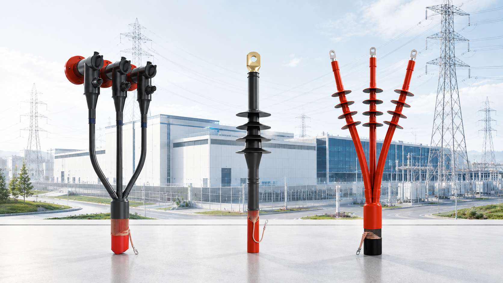
Data centers are designed around one basic requirement: power must remain available.
A lot of attention therefore goes into transformers, MV switchgear, UPS systems, generators, protection systems and redundancy.
But there is another part of the electrical network that deserves the same attention:
They may be relatively small components in the overall electrical system, but they sit at critical connection points between the MV cable and equipment such as switchgear, transformers and RMUs.
For a data center developer, the question should therefore not simply be:
“Which termination are we using?”
The better question is:
“Is the complete cable–termination–equipment interface designed and installed for long-term reliability?”
That difference matters.
Depending on the electrical architecture and local utility network, a data center may receive or distribute power at medium voltage, commonly using systems such as 11 kV, 22 kV or 33 kV.
MV cables then connect different parts of the electrical infrastructure.
At every point where a cable ends and connects to equipment, the cable termination has an important job.
It must:
This is why a termination should not be treated simply as an accessory added at the end of a cable.
It is part of the MV electrical system.
1. Start With the Complete Cable and Equipment Interface
One common mistake is selecting a termination mainly by voltage level and conductor size.
For example:
33 kV + 400 mm² cable = 33 kV termination for 400 mm².
That is only the starting point.
The termination manufacturer or supplier should also understand the actual cable construction.
Important information includes:
The equipment interface is equally important.
A cable terminating into air-insulated switchgear is not necessarily the same application as a cable connecting to a transformer bushing or compact screened switchgear.
For critical infrastructure, selection should be based on the complete interface — not only the cable size written on the purchase order.
Inside a screened MV cable, the electrical field is controlled by the cable's insulation and semiconductive screen.
When the cable is prepared for termination, that screen has to end.
At this screen cut-back point, electrical stress becomes concentrated.
The termination system is designed to manage this stress and allow the electric field to transition safely from the screened cable into the termination.
Different technologies achieve this in different ways.
These may include:
The technology can differ.
The objective does not:
control the electrical field reliably over the service life of the installation.
This is one reason correct cable preparation and correct positioning of stress-control components are so important.
A well-designed termination can still perform poorly if it is installed incorrectly.
MV cable preparation is skilled work.
Small mistakes during preparation can create problems that may not necessarily become visible immediately.
Typical concerns include:
For data centers, this leads to an important procurement lesson:
Do not evaluate only the termination kit. Evaluate the installation system around it.
That means installer competency, installation instructions, correct tools, supervision, inspection and documentation should all form part of the quality process.
For MV accessories up to 36 kV class, IEC 60502-4:2023 is an important international reference.
It specifies type-test requirements for accessories used on extruded-insulation power cables from 3.6/6 (7.2) kV up to 18/30 (36) kV.
For projects following IEEE requirements, IEEE 48-2020 provides test procedures and requirements for AC cable terminations used on shielded cables.
The important point for developers and consultants is simple:
Ask for evidence of testing applicable to the actual product being offered.
Do not stop at:
“Our termination complies with IEC.”
Ask:
This gives the technical team something much more useful than a compliance statement in a brochure.
Data-center electrical rooms are controlled environments, but installation conditions can still vary considerably.
Terminations may be installed in:
Temperature, humidity, dust, condensation and available clearances can all influence the application.
Outdoor installations bring additional requirements related to weather, pollution and moisture.
The termination therefore needs to be selected for where it will actually operate, not simply for its voltage rating.
Modern data centers often use compact electrical layouts.
That makes cable routing and termination space important.
Before finalising the system, engineers should check:
A termination may be electrically suitable but still create installation problems if the available space was not considered during design.
This becomes particularly important with large conductor sizes and multiple cables per phase.
Cable accessory selection should therefore happen during engineering — not at the last stage of procurement.
Not every MV connection needs a conventional exposed termination.
For equipment designed with suitable bushings, screened separable connectors can provide a compact, screened and touch-proof connection.
These are commonly associated with equipment such as:
But compatibility matters.
The connector needs to match the equipment bushing interface, cable dimensions, conductor size, voltage rating and current requirement.
A connector that physically appears to fit is not enough.
The complete interface must be verified.
The electrical connection between the cable conductor and equipment is another critical part of the termination.
Depending on the design, this may use:
Correct conductor preparation and installation are essential.
For mechanical connectors, the connector must be suitable for the conductor material and conductor size specified.
For compression systems, the correct lug, die and crimping procedure must be used.
The insulation system around a termination cannot compensate for a poor conductor connection.
Large data-center developments can involve many MV cable connections across multiple buildings, phases or expansion stages.
Allowing too many different termination designs, cable constructions and installation methods can make quality control more difficult.
Where practical, developers can standardise:
This can make procurement easier and, more importantly, make installation quality more consistent across the project.
For critical infrastructure, the termination should not disappear from the records once the switchgear panel is closed.
Each installed termination should ideally be traceable.
Project documentation can include:
This information becomes useful during future maintenance, troubleshooting and expansion.
For a large data-center campus, good documentation today can save considerable time years later.
Before approving an MV termination system, ask these questions:
1. Is the termination suitable for the actual cable construction?
Not just voltage and conductor size.
2. Is it compatible with the switchgear or transformer interface?
Check dimensions, clearances and bushing/interface requirements.
3. Has the product been tested to the relevant standard?
Review the actual type-test evidence.
4. Who will install it?
MV accessory installation should be treated as skilled work.
5. Is the installation procedure controlled?
Cable preparation, component positioning, conductor connection, earthing and sealing should follow defined instructions.
6. Is there enough installation space?
Check this before equipment reaches site.
7. Is the installation traceable?
Record what was installed, where, when and by whom.
Select the right termination. Match it correctly to the cable and equipment. Install it correctly. Test it properly. Document it.
That is how small components contribute to reliable power infrastructure.
COMPAQ International designs and manufactures cable accessory solutions for power distribution networks and critical electrical infrastructure.
The portfolio includes heat-shrink, cold-shrink and pre-moulded cable joints and terminations, along with screened separable connectors and related cable accessories for medium-voltage applications.
COMPAQ works with utilities, EPC contractors, infrastructure developers and industrial projects across international markets, with engineering and manufacturing capabilities focused on reliable cable connections.
For data-center projects, COMPAQ can support cable-accessory selection based on the actual cable construction, voltage class, equipment interface and installation conditions rather than treating the termination as a standard catalogue item.
Because reliable power depends on reliable connections.

Need Help?
Our experts are ready
Our experts are available for on-site support, remote
guidance and tailored engineering.